2月 22, 2024
5620

Transistors are indispensable components in electronic circuits, playing vital roles as amplifiers, switches, and more. Among the various transistor types, NPN (Negative-Positive-Negative) and PNP (Positive-Negative-Positive) transistors are commonly used, distinguished by the arrangement of their semiconductor layers. Understanding the differences between NPN and PNP transistors is essential for designing and troubleshooting electronic circuits effectively.

Transistors are fundamental components in electronic circuits, serving as amplifiers, switches, and more. NPN (Negative-Positive-Negative) and PNP (Positive-Negative-Positive) transistors are two common types, differentiated by the arrangement of their semiconductor layers.

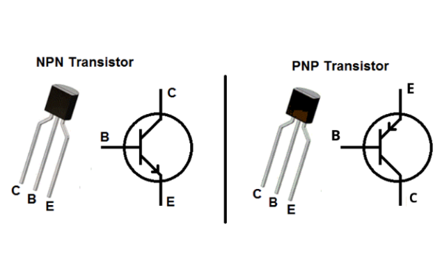
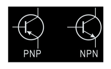
The symbol for an NPN transistor typically consists of an arrow pointing outward from the base region, denoting the direction of conventional current flow. This arrow represents the flow of positive charge carriers, which move from the base terminal to the emitter terminal when the transistor is forward biased. The three terminals of an NPN transistor are the emitter (e), base (b), and collector (c). In a schematic diagram, the emitter is typically shown as a downward-pointing arrow, the base as a straight line, and the collector as an upward-pointing arrow.
Conversely, the symbol for a PNP transistor features an arrow pointing inward towards the base region, indicating the direction of conventional current flow. In this case, positive charge carriers move from the emitter terminal to the base terminal when the transistor is forward biased. Like the NPN transistor, a PNP transistor also has three terminals: emitter (e), base (b), and collector (c). However, the direction of the arrows in the symbol is reversed compared to an NPN transistor. In a schematic diagram, the emitter is represented with an upward-pointing arrow, the base as a straight line, and the collector as a downward-pointing arrow.
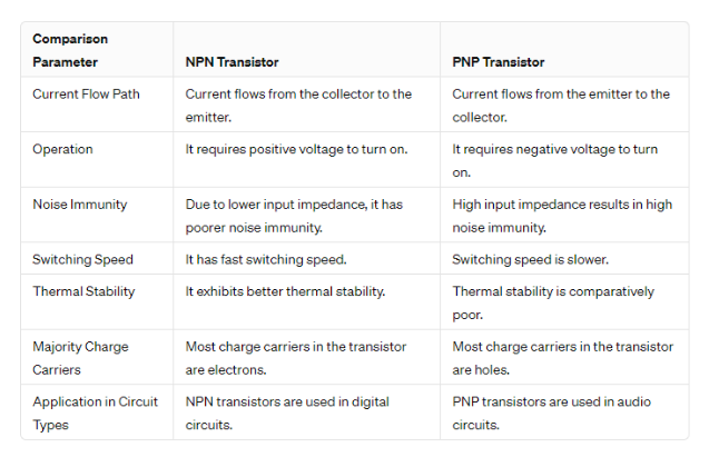
In the realm of transistor switches, the disparity between NPN and PNP transistors lies in their response to input signals. A PNP transistor switches on when a low signal is applied to its base terminal relative to its emitter terminal. Conversely, an NPN transistor activates when a high signal is applied to its base terminal compared to its emitter terminal. This fundamental distinction determines the conditions under which each type of transistor conducts current through its collector-emitter path.
The symbols and designations used for NPN and PNP transistors provide insight into their terminal polarities. In PNP transistors, the "P" denotes the positive polarity of the emitter terminal relative to the base terminal, while the "N" signifies the negative polarity of the base terminal concerning the emitter. On the other hand, for NPN transistors, the "N" designation indicates the negatively charged material forming the emitter and collector regions, while the "P" represents the positively charged base region.
The construction of NPN and PNP transistors involves layers of semiconductor materials arranged in specific configurations. In PNP transistors, the semiconductor layers consist of P-type material sandwiched between N-type layers, where the majority charge carriers are holes. Conversely, NPN transistors feature layers of N-type material sandwiched between P-type layers, with electrons serving as the majority carriers. This distinction in material structure underpins the operational disparities between NPN and PNP transistor switches.
Understanding the inherent characteristics and operational behaviors of PNP and NPN transistors is crucial for selecting the appropriate transistor type for a given application. Whether the requirement is to sink or source current, the choice between PNP and NPN transistors depends on factors such as load configuration, voltage levels, and desired circuit functionality.
PNP transistors find widespread use in applications where the primary requirement is to sink current, meaning the transistor conducts current when its base is at a lower voltage relative to its emitter. This configuration is particularly advantageous in scenarios where the load needs to be connected between the collector and a positive power supply. Some common applications of PNP transistors include:
Switching Circuits: PNP transistors are extensively used in switching circuits, especially in situations where the load is connected to a positive voltage source. By applying a low voltage signal to the base relative to the emitter, the PNP transistor conducts current from the collector to the emitter, effectively switching the load on.
Darlington Pair Configurations: PNP transistors are often employed in Darlington pair configurations, where two transistors are connected in series to provide high current gain. This arrangement is useful in applications requiring high power amplification or in driving high-current loads.
Conversely, NPN transistors serve as current sources, conducting current when a voltage applied to the base is higher than that at the emitter terminal. This property makes NPN transistors suitable for applications where the load needs to be connected between the collector and ground. Some common applications of NPN transistors include:
Amplification Circuits: NPN transistors are extensively used in amplifier circuits, where they amplify small input signals into larger output signals. In these circuits, the NPN transistor acts as a current source, allowing current to flow from the collector to the emitter in response to variations in the base current.
Digital Logic Circuits: NPN transistors are integral components in digital logic circuits, such as those used in computers and microcontrollers. They are employed in configurations such as inverters, NAND gates, and NOR gates, where they facilitate signal amplification and logic operations.
BC547 transistors fall under the NPN category. Consequently, when the base pin is grounded, both the collector and emitter terminals remain open (reverse biased). However, once a signal is applied to the base pin, they become closed (forward biased), allowing current flow.
The 2N7000 transistor is neither NPN nor PNP; rather, it is a type of field-effect transistor (FET), specifically a metal-oxide-semiconductor field-effect transistor (MOSFET). MOSFETs are a distinct type of transistor that operate based on the movement of majority charge carriers within a conducting channel controlled by an electric field. Therefore, the classification of NPN or PNP does not apply to MOSFETs like the 2N7000.
The CL100 transistor is an NPN (Negative-Positive-Negative) type transistor. In NPN transistors like the CL100, the majority charge carriers are electrons, and current flows from the collector to the emitter when a positive voltage is applied to the base relative to the emitter.
Low-Side Switching: NPN transistors are frequently utilized in low-side switching configurations, where the load is connected between the transistor's collector and ground. This arrangement is common in applications such as LED drivers, relay control circuits, and motor control.
High-Speed Digital Circuits: Due to their fast switching speeds and low input capacitance, NPN transistors are well-suited for use in high-speed digital circuits. They find applications in logic gates, digital amplifiers, and microprocessor interfaces.
High-Frequency Analog Circuits: NPN transistors are preferred in high-frequency analog circuits such as RF amplifiers, oscillators, and frequency multipliers. Their inherent characteristics, including low noise and high gain, make them ideal for amplification at radio frequencies.
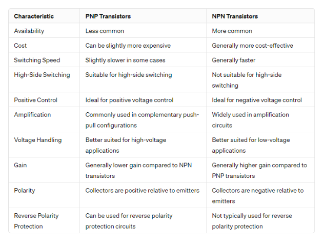
High-Side Switching: PNP transistors are commonly employed in high-side switching configurations, where the load is connected between the transistor's emitter and the positive supply voltage. This setup is suitable for applications requiring positive voltage control, such as battery-powered devices and automotive electronics.
High-Voltage Applications: PNP transistors are preferred in high-voltage applications due to their ability to handle higher voltages compared to NPN transistors. They are used in voltage regulators, switching power supplies, and voltage level translators.
Complementary Push-Pull Amplifiers: PNP transistors are often used in complementary push-pull amplifier configurations alongside NPN transistors. This arrangement allows for efficient amplification of both positive and negative halves of the input signal, making them suitable for audio amplifiers, power amplifiers, and class B amplifier stages.
As mentioned, the schematic symbols for NPN and PNP transistors are similar, but the orientation of the arrow on the emitter indicates the transistor type. In an NPN transistor symbol, the arrow points outward from the base, while in a PNP transistor symbol, the arrow points inward toward the base.
Using a multimeter in diode test mode, you can determine the polarity of the transistor junctions. For an NPN transistor, the base-emitter junction will show a forward bias (low resistance) when the positive probe is connected to the base and the negative probe to the emitter. The base-collector junction will show a reverse bias (high resistance). In contrast, for a PNP transistor, the base-emitter junction will show a forward bias when the negative probe is connected to the base and the positive probe to the emitter, while the base-collector junction will show a reverse bias.
NPN transistors typically have a higher collector-base breakdown voltage compared to their emitter-base breakdown voltage, while PNP transistors have a higher emitter-base breakdown voltage compared to their collector-base breakdown voltage. Measuring these breakdown voltages can help identify the transistor type.

In conclusion, the differentiation between NPN and PNP transistors lies in their structural arrangement and operational characteristics. While NPN transistors are commonly used for sinking current and in high-speed digital circuits, PNP transistors find applications in sourcing current and high-voltage scenarios. Both types of transistors have their distinct advantages and applications, making them invaluable components in modern electronics. Additionally, the ability to interchange or run transistors in parallel further enhances their versatility and utility in various circuit designs.
Are NPN and PNP transistors interchangeable?
In certain cases, NPN and PNP transistors can be substituted for one another if they possess similar characteristics; however, this interchangeability requires reversing the power supply polarity and may necessitate adjustments to surrounding circuitry to ensure proper functionality and performance.
How to convert PNP to NPN?
Converting a PNP transistor circuit to its NPN equivalent involves replacing the PNP transistor with an NPN transistor having similar characteristics and then reversing the power supply polarity. This requires connecting the base, collector, and emitter terminals of the NPN transistor in the same configuration as the PNP transistor in the circuit diagram, and then reversing the polarity of the power supply.
How do you connect two NPN transistors?
Connecting two NPN transistors in series involves creating a series connection between the transistors, typically with the collector of the lower transistor connected to the emitter of the upper transistor. This arrangement allows for the load or circuit to be controlled by two different input signals. Each transistor can be individually controlled by its respective input signal. When one transistor is turned on by its input signal, it allows current to flow through the series connection, turning on the next transistor and ultimately powering the load. However, it's important to note that both input signals need to be active (turned on) for the load to be powered. This configuration provides redundancy and increased reliability in certain applications, as either input signal can independently turn off the load, ensuring fail-safe operation.
Can you run transistors in parallel?
Yes, transistors can be run in parallel in electronic circuits. Running transistors in parallel is a common practice used to increase the current-handling capacity of a circuit, distribute heat more evenly, and provide redundancy for improved reliability.
When transistors are connected in parallel, each transistor shares a portion of the total current flowing through the circuit. This arrangement allows for higher total current handling capability compared to using a single transistor. Moreover, running transistors in parallel can help prevent any individual transistor from sustaining damage due to excessive current.